From years of working on hard real-time embedded projects, one lesson stands out: don’t just chase average throughput. Worst-case execution time must be predictable, jitter has to be minimized, and failures need to be contained and degraded gracefully instead of taking down the whole system. Below are practical optimization approaches across architecture, memory, and instruction levels, plus two widely used architecture prototypes from real projects.
1. Architecture Design: Set the Real-Time Ceiling at the Top Level
Poor architecture choices can never be fully fixed by code-level tweaks. The core idea is to minimize dynamic behavior, lock down everything possible at design time, and build solid fault isolation.
Approach 1: Time-Triggered Static Scheduling (TTA)
Instead of traditional priority-based preemptive scheduling, predefine the start time and maximum execution window of every task at compile time into a global time-slot schedule. Tasks run exactly on schedule, and stop when their window ends.
- Benefits: Eliminates preemption overhead and priority inversion entirely. Task start jitter can be pushed down to the hundreds-of-nanoseconds range, and WCET is fully calculable.
- Use cases: Avionics (ARINC653), automotive functional safety (ISO26262), 5G physical layer synchronization, and any scenario with extremely strict timing requirements.
Approach 2: Static Core Binding + Master-Slave Isolation
For multi-core systems, avoid SMP dynamic scheduling — task migration causes cache thrashing and severe scheduling jitter. Bind tasks permanently to cores with no migration. Assign one master core for control and scheduling, and dedicate the rest purely to computation.
- Master core: Handles global timing, task distribution, peripheral I/O, and fault monitoring; owns the interrupt controller.
- Slave cores: All non-critical interrupts disabled; each core runs a single compute task with zero context switching. Inter-core communication uses shared-memory ring buffers + inter-core interrupts, no mutexes, no blocking.
Approach 3: Split Control Plane / Data Plane Architecture
Physically separate the low-latency data path from management and control workloads, running them on dedicated cores so they never interfere.
- Data plane: Dedicated cores, highest priority, code and data resident in on-chip memory. No syscalls, no dynamic memory, no logging in the critical path — pure computation and high-speed I/O.
- Control plane: Runs on separate cores, handling protocol stacks, configuration, logging, and debugging. Even if it crashes or restarts, the data path keeps running uninterrupted.
Approach 4: Layered Fault Tolerance with Graceful Degradation
Build four layers of protection from hardware to application, isolating faults at each level. The system can degrade gracefully instead of failing completely.
- Hardware layer: ECC memory, independent watchdog, dual-core lockstep, bus error detection.
- Kernel layer: MPU memory isolation between tasks, hardware stack overflow detection, task timeout monitoring.
- Service layer: Input validation, state machine boundary checks, redundant copies of critical data.
- Application layer: Three-level degradation: full functionality → non-core features disabled (core only) → safe standby state.
2. Memory Access Optimization: Eliminate the Biggest Jitter Source
Roughly 90% of latency jitter in embedded systems comes from memory access. On-chip SRAM can be tens of times faster than external DDR, and cache misses or data copies introduce huge variability.
Approach 1: Full Residence in Tightly Coupled Memory (TCM)
TCM is single-cycle on-chip SRAM with no cache replacement logic — access latency is 100% deterministic, the gold standard for hard real-time systems. Place ISRs, core compute functions, and hot data entirely in TCM via linker scripts at compile time. Keep the active working set for current processing in TCM; only bulk, non-hot data goes to DDR. Keep the entire critical path off DDR entirely to eliminate memory access jitter.
Approach 2: Ping-Pong Buffers + Zero-Copy Full Pipeline
Pass only pointers through the data pipeline, never copy full payloads. Use dual buffers to overlap capture, processing, and output in parallel. While the DMA writes to buffer A, the CPU processes the previous frame in buffer B. Swap buffer pointers when done — zero copy, zero overhead. All inter-module and inter-core communication uses address + length, no memory copies.
Approach 3: Cache Locking + Partitioned Isolation
For architectures without TCM, lock critical code/data into L1 cache so it’s never evicted. Partition cache across cores to avoid cross-core cache thrashing. Lock interrupt handlers and core algorithms into L1 instruction/data cache. Use cache coloring to assign each core its own cache line region, eliminating interference during parallel execution.
Approach 4: Asynchronous DMA + Compute/Memory Overlap
Use DMA to move data in the background while the CPU computes, hiding DDR access latency entirely behind computation time. Process large data frames in blocks: DMA fetches the next block while the CPU processes the current one. Use chained DMA descriptors to move multiple blocks automatically without CPU intervention. DMA completion signals via low-priority interrupts, so it never interrupts the main compute flow.
3. Instruction-Level Tuning: Stabilize Execution Time & Maximize Efficiency
For the most critical code paths, eliminate execution uncertainty at the instruction level, make cycle counts fully predictable, and squeeze as much performance as possible out of the hardware.
Approach 1: SIMD Vectorization + Full Fixed-Point Arithmetic
Leverage the processor’s SIMD extensions (ARM NEON, DSP SIMD, RISC-V V extension) to process multiple data points per cycle. Replace floating-point with fixed-point arithmetic to avoid soft-float uncertainty and exceptions. Rewrite compute-heavy functions (filtering, FFT, matrix math) with SIMD intrinsics. Standardize on Q-format fixed-point arithmetic; remove all floating-point instructions from critical paths.
Approach 2: Branch Elimination + Static Control Flow
Most embedded MCUs/DSPs have weak or no branch prediction. Branches cause pipeline stalls and variable execution time. Replace multi-layer if-else chains with lookup tables. Replace short branches with conditional move (CMOV) instructions where available. Fix loop iteration counts in critical code; avoid variable-length loops. No function pointers or virtual calls in critical paths — all call paths are fixed at compile time.
Approach 3: Software Pipelining + Hand-Written Assembly
For VLIW DSP architectures, unroll loops to expose instruction-level parallelism, and use software pipelining to achieve near-single-cycle loop throughput. For the most latency-sensitive functions, write assembly by hand to precisely control instruction ordering and register allocation. Manually unroll core loops, fill delay slots, and schedule multi-issue parallel execution. Write ISRs and core algorithms directly in assembly with consistent stack frames and register-first variable usage. Avoid overly aggressive compiler optimizations that reorder instructions and introduce execution time variability.
4. Reference Architecture Prototypes
Prototype 1: Multi-Core DSP 5G Physical Layer Processing
For high-speed signal processing use cases like communications and radar: 8-core DSP, master-slave architecture, pipelined processing.
- Key design: Master core handles scheduling and control; 6 slave cores are statically assigned to pipeline stages. Inter-core data transfer uses shared-memory ping-pong buffers, zero-copy and lock-free.
- Optimization combo: Time-triggered static scheduling + TCM-resident core code + SIMD/software pipelining acceleration. Typical metrics: Per-frame processing jitter <1μs, end-to-end latency <100μs, single-point failure does not crash the system.
Prototype 2: Industrial MCU Functional Safety Control Architecture
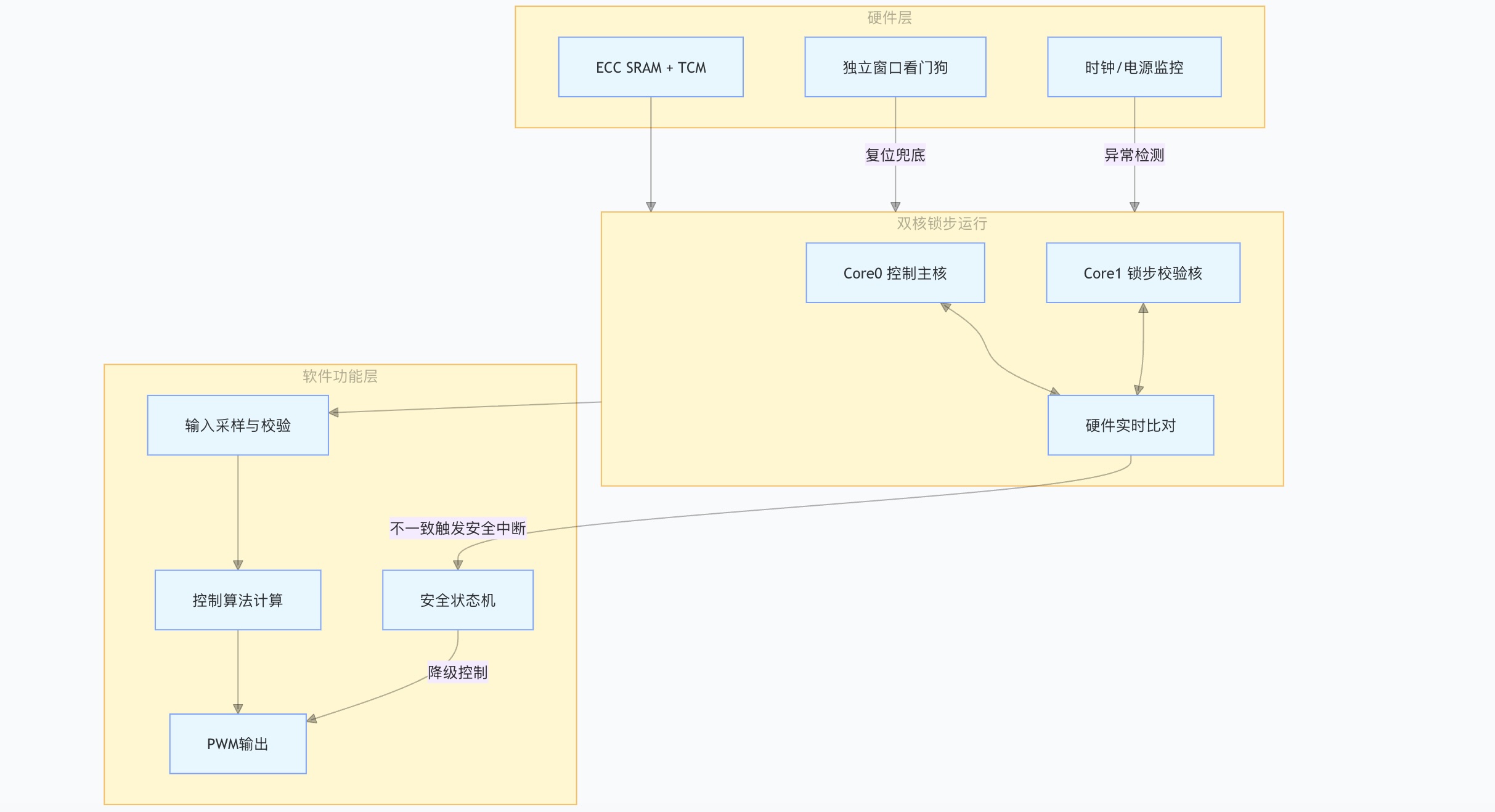
For industrial control and automotive electronics scenarios: dual-core lockstep + static periodic scheduling.
- Key design: Both cores execute identical code in lockstep; hardware compares results in real time, and triggers a safe state on mismatch. Scheduling uses static time tables (AUTOSAR OS style) with no preemption.
- Optimization combo: Static time scheduling + dual-core lockstep fault tolerance + TCM-resident algorithms + fixed-point branch-free code. Typical metrics: Control cycle jitter <0.1μs, meets SIL3 functional safety, fault response time <1ms.